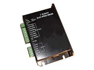
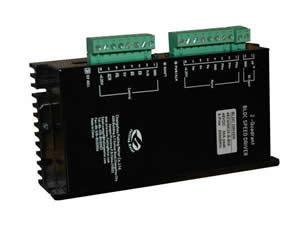
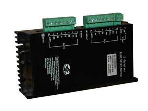
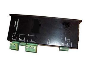
Brushless Motor Driver
1. Product Introduction
Basic Components
Master chip, inverter power transistor circuit, function control circuit, protection circuit, speed control circuit
Working Principle
The current position of the rotor is detected by the Hall sensor. Then, the power-on sequence of the power transistors in the inverter can be determined according to the stator windings. Current flows through the motor coil in order, thus generating forward or reverse rotating magnetic field. This magnetic field interacts with the rotor magnet, making the motor rotate clockwise or counterclockwise.
2. Certification
Our brushless motor driver meets the requirements of CE and RoHS standards. We can also apply for UL certification as per customer needs.
3. Optional Accessories
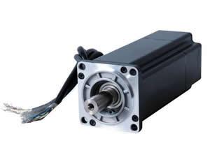
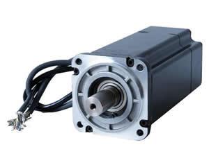
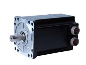
The motor can be equipped with a gearbox, encoder, brake, external drive and built-in drive. The output shaft can be equipped with pulley or gear according to customer request. Connector can be installed for the leads. In addition, the length and diameter of the shaft as well as the length and color of the lead can be designed as per customer requirements.
4. Notes
A. When selecting a drive according to the operating voltage of the motor, the voltage can not exceed the drive's use range.
B. The peak current of the selected drive should approach or exceed the value calculated according to the following formula: Peak current = rated motor power × 4 / rated motor voltage.
C. As the brushless motor driver has speed setting and PI control, it should match the motor's maximum speed and number of poles. The drive model should be recommended by our staff.
D. Since the motor winding lead may interfere with the Hall signal line, they should be wired separately. When the winding lead is longer than 500mm, a shielded wire is suggested to use so as to separate from the Hall signal wire.
Related Names
Brushless Electric Machinery Driver | Driver of Motor without Brush | Brushless Motor Machine Driver | Driver of Electric Device without Brush
Changzhou Fulling Motor Co., Ltd.


